DESCRIPTION
Connects mid rails to uprights on a straight and level guard rail. Uprights must be precisely aligned at 90° to the cross rails.
IMAGE
DESCRIPTION
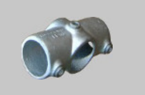
Typically used at the top-centre of frame-like structures such as storage racking and climbing frames.
IMAGE
DESCRIPTION
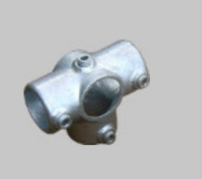
Connects top rail of a straight and level guard rail to an upright at 90°.
IMAGE
DESCRIPTION
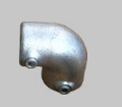
Connects two top rails at 90° to each other to a vertical corner post.
IMAGE
DESCRIPTION
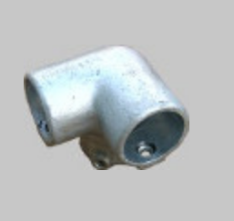
Connects upright to top rail or mid rail to upright on straight and level railings.
IMAGE
DESCRIPTION
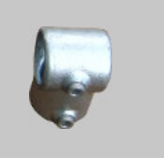
Connects mid rails to uprights at a 90° corner post. In the other orientation, it fixes an intermediate horizontal tube to an outer rail in the top of a frame-like structure.
IMAGE
DESCRIPTION
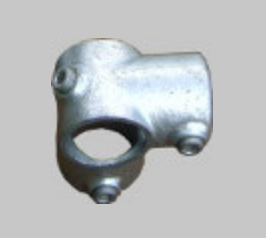
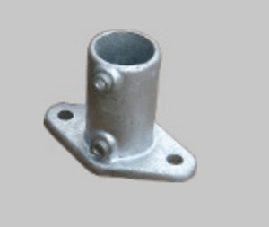
Bolt to the floor to provide structural base plates for vertical posts. In guardrails, the fitting should be aligned with the bolt holes at 90° to the direction of the railing for maximum strength.
IMAGE
DESCRIPTION
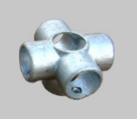
An intersecting internal joint typically used in frame structures.
IMAGE
DESCRIPTION
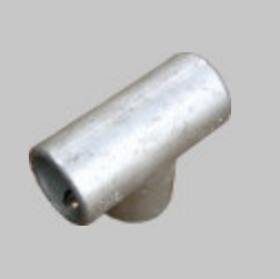
Connects top rail to upright at 90°. Top rail tubes can be joined end to end inside.
IMAGE
DESCRIPTION
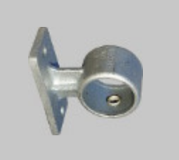
Typically for wall-mounting hand rails. Not suitable as a base mount for guard rails or dependent structures.
IMAGE
DESCRIPTION
Used in pairs to create a horizontal hand rail corner at an angle between 85° & 235° off a vertical post.
IMAGE
DESCRIPTION
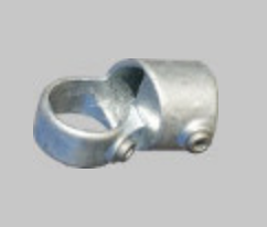
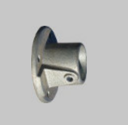
Can be used to terminate a cross rail to a wall or as a base plate for non load-bearing structures eg. a bench.
IMAGE
IMAGE
DESCRIPTION
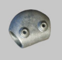
for creating an angled corner at 15° – 60°.
IMAGE
DESCRIPTION
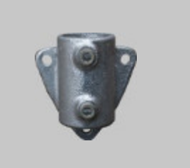
For mounting the upright tube of a guard rail as close as possible to a slope or staircase to minimise the gap.
IMAGE
DESCRIPTION
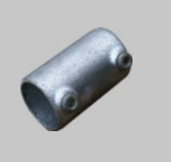
Connects tubes end to end. Not a structural joint.
IMAGE
DESCRIPTION
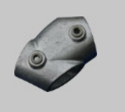
for creating an angled T-junction at 30° – 60°.
IMAGE
IMAGE
DESCRIPTION
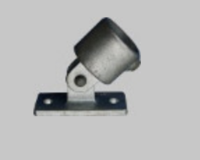
Bolts to the ground to provide a variable angle base plate up to 85°. Non-structural fitting, not to be used as a base plate for guard-rails or dependent structures and not designed to withstand lateral loadings.
IMAGE
DESCRIPTION
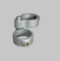
Clamp number 138 has a hole to receive the spigot of clamp number 140, which enables them to act as a hinge. Each clamp takes a vertical tube – one for the gate post and the other for the gate. For two hinges, you would therefore use two pairs of 138 & 140 clamp.
IMAGE
DESCRIPTION
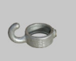
Hooks for hanging a chain barrier on upright posts.
IMAGE